
The way the template is constructed is that in the template's design the outer and inner antenna's are aligned at the top, I prefer that they are aligned in the middle and have equal spacing at the top and bottom (doesn't make a difference on performance). I originally tried to make the correct holes without using the template and they came out terrible, they were not 90° and getting the spacing and alignment correct was a huge pain.
#Wxtoimg instruction pdf
Make the Template: Either make a PDF Cutting Template from the calculator, or use the existing one included in the GitHub repository and print out the PDF, make sure that you are printing the actual size and that the "shrink to fit" options are NOT selected for your printer.

To avoid mistakes, don't start drilling until all the holes are marked You can also see that the two different antenna's are color coded: Blue for the large outer, Green for the smaller inner, this color coding comes in handy for not getting confused and getting the right dimensions and lengths. One of the images above is a screenshot of the results for our antenna, our hole drilling template comes from the same site (or the "Hole Cutout Guide.pdf" file in the GitHub repo). I used metric for the plans and dimensions because it just made the measuring easier and was simplier then trying to convert the metric in the calculator to fractions of inches. The dimensions came from this particular site: which allows you to enter in the parameters of the frequency you are trying to tune to, along with some info about your materials, and it gives you not only the dimensions of everything you need but a PDF cutting guide which you'll need in the next steps. This adapter ( ) looks like it'll go right from the card to the coax without the BNC middlemanĪttached to this page is the SketchUp diagram of the antenna with dimensions added, (my cable curves are a little ugly but give the general idea, I am terrible at curves in Sketchup). I then also needed a BNC to Coax Cable Adapter (which I got from Radio Shack). I picked up this adapter when I bought the SDR card in the amazon package, it's a MCX to BNC ( ).
#Wxtoimg instruction software
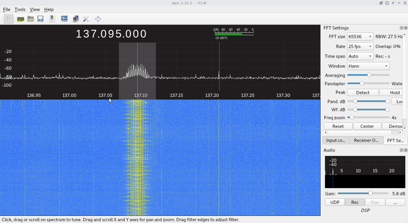
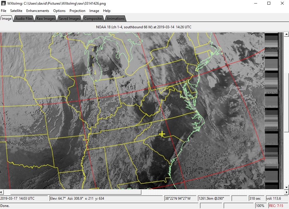
This means you can pick up the signal from a NOAA satellite when it is just above the horizon, receive it as it tracks across the sky (~10 to 15 mins for the pass), and will lose the signal when it's just about set on the other horizon.įinally, we'll go over the various pieces of software we will use to find the satellites, listen to them, and then take that transmission and turn it in to a picture like the one on this page. The QFH is very easy to make and is an omnidirectional antenna, meaning that you don't have to aim it to have it pick up the signals and it has excellent performance across the whole sky.

You can build QFH Antenna's of various sizes that are sensitive to different frequency bands, but we'll be focusing on the dimensions for 137.5 MHz in this instructable. This is where the QFH Antenna comes in, it's actually two antennas, a small one inside a bigger one, that is of the proper dimensions so that it blocks out surrounding interference and receives signals very well on the 137.5 MHz frequency band that the NOAA satellites transmit around. The SDR tuner will allow us to receive the transmission but we need a good antenna tuned to the APT signals in order to receive a clear picture. So a small, cheap ~$15 radio dongle, containing two chips the RTL2832U and R820T tuner IC, is capable of recieving radio signals that cover a broad range, 25MHz-1700MHz, of the spectrum. It all starts with a simple SDR (Software Defined Radio) which is a radio where the traditional and complicated parts, the modulators and amplifiers, are now done by computer software rather than the hardware. This instructable covers everything you'll need to get started in being able to receive the APT (Automatic Picture Transmission) signals from the NOAA Satellites (NOAA-15, 18, and 19) flying overhead (and can be a foundation for listening to other satellites as well).


 0 kommentar(er)
